C1 F
High-Performance Horizontal Ceiling Mount

High Performance Cased Flush Horizontal Bottom Return

Part Number: C1-F

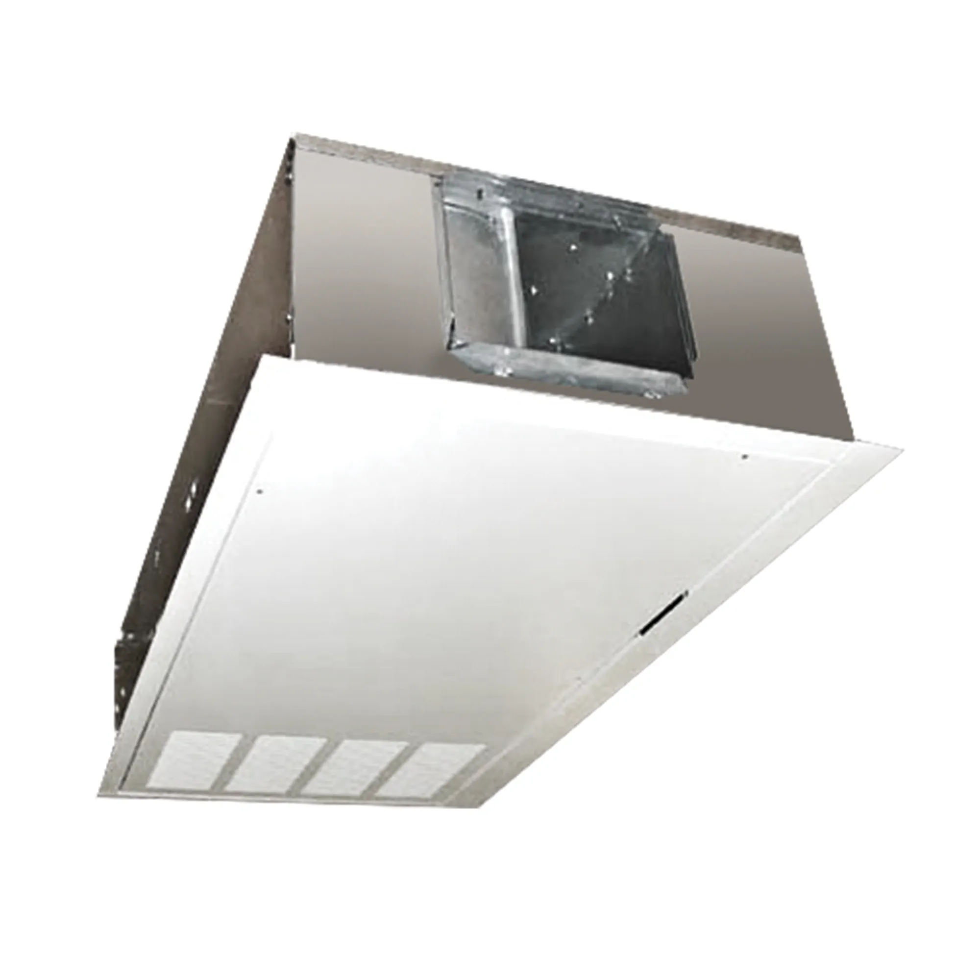
The Cased Flush Horizontal (C1-F) is a horizontal, high-static (up to .50ESP), fan coil. The C1-F is horizontally ducted and has a standard bottom return-air. The C1-F comes with a coil, blower/motor assembly with quick-connect plug and a galvanized steel, powder-coated epoxy drain pan covered with ⅛-inch thick insulation. The galvanized steel cabinet is insulated with ½-inch thick, over three pound density, neoprene-coated fiberglass. The swing-down access panel of the C1-F allows fast and easy filter removal and routine maintenance. The access panel and frame are finished with a durable soft-white powder-coated epoxy. This unit is easily mounted in drop down ceilings and soffits.

Cooling Capacity

C1 Series Hi-Performance Horizontal fan coils have been rated in accordance with AHRI Standard 440-2005 for room fan-coil air-conditioners and are certified by AHRI to meet the following product performance ratings:

Based on 80°F DB and 67°F WB EAT, 45°F EWT, 10°F temperature rise, high fan speed. Motor voltage 115/1/60 power source.
Air flow under dry coil conditions. Water pressure drops shown in feet of water.

Heating Performance

Based on 70°F DB EAT, 180°F EWT, 40°F temperature drop, high fan speed. Motor voltage 115/1/60 power source.
Air flow under dry coil conditions. Water pressure drops shown in feet of water.

Features

  • 400 to 800 CFM
  • High-static direct-drive fan coil, constructed of heavy-gauge galvanized steel and insulated with 1/2″ thick, over three-pound density, neoprene-coated fiberglass
  • The unit is a horizontally ducted fan coil which is aligned flush with the ceiling
  • Ideal for horizontal applications that require either a drop-ceiling or soffit installation
  • Swing-down access panel allows for fast and easy filter removal and routine maintenance
  • Bottom return-air standard
  • Heavy-gauge galvanized steel cabinet insulated with 1/2″ thick, over three-pound density, neoprene-coated fiberglass
  • Coils are manufactured of copper tube with aluminum fins and are 100% underwater pressure tested to 350 PSI with a 300 PSI working pressure
  • Galvanized drain pan is finished with a powder-coated epoxy, 1/8″ thick insulation and features primary and secondary drain connections
  • Three-speed, 115/1/60 motor with quick-connect plug
  • Easy slide-out, blow-through blower and motor assembly
  • Controls and motors are factory-wired and terminated in a junction box for single-point power supply
  • One-inch fiberglass, throwaway filter
  • One-inch duct collar on return- and supply-air openings
  • High-static motor is designed for jobs where high-static pressure (0.50 max) is required
  • Protective covers keep the grille openings free of debris during shipment and construction
  • Individually tagged, crated and shipped as scheduled for installation
  • ETL and AHRI certified; 100% factory tested

Accessories

Accessories Options

  • Valve package controls – wide selection of factory-mounted valves and controls
  • Supply grilles
    • Single-deflection
    • Double-deflection
  • Thermostats
  • Condensate float switch
  • Condensate pumps
  • Controls – wide selection of factory-mounted valves and controls

Dimensions

Options

Systems

  • DX
  • Chilled-Water
  • Hot-Water
  • Electric Resistance
  • Steam

In any combination of the above

Insulation

  • Thickness up to 1″
  • Fiberglass
  • Foil-face
  • Elastomeric

Coil

  • Copper fins/tubes
  • Phenolic-coated
  • Stainless-steel end plates
  • Right, left connections or opposite end connection
  • TXV – factory-mounted
  • Freeze protection
  • Custom fin spacing

Drain Pan

  • Stainless-steel
  • Extended
  • Drip tray
  • Condensate float switch
  • Condensate pumps

Cabinets

  • Marine duty

Electrical

  • Motors
    • 115, 208, 230 and 277
    • Single or three phase
    • 50 or 60Hz
    • ECM
  • Line or low voltage
  • 1 to 9 kW electric resistance heat
  • Disconnects
    • Fused
    • Non-fused
  • Condensate float switch
  • Condensate pumps
  • Thermostats

Further Information

• All sizes shown in inches.
• Right-hand unit shown, left-hand unit opposite.
• Coil connections determined by facing the supply-air opening.
• Electrical junction box is located on the same side as the coil connections.
• Unit must be installed level and condensate drain lines should be trapped.
• Drain pan is powder-coated epoxy with a 1/8” thick closed-cell insulation and has 3/4” NPT primary and secondary drain connections.
• Entire cabinet, scroll and blower wheel are heavy-gauge, galvanized steel.
• Coil Connections: 1/2” CW on C1004-006, 3/4” on C1008. 1/2” HW on C1004-008.