Low Static Vertical Slope Top Painted Cabinet (f1 S)
Vertical Wall Mount

Low-Static Vertical Slope Top Painted Cabinet

Part Number: F1-S

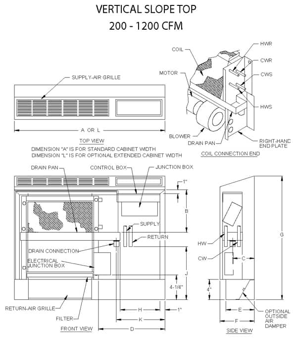
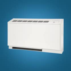
The Vertical Slope Top (F1-S) is a low-static (up to .25 ESP) fan coil is in a cabinet with sloping top and solid-side panels. Units may be mounted side by side for long corridor applications. The full sloping top discourages placement of books or other objects over the stamped louvered discharge grilles. The vertical upflow design is ideal for heating and cooling requirements in office buildings, college dormitories, churches, hospitals, hotels and motels. The F1-S fan coil comes with a coil, blower/motor assembly with quick-connect plug and a galvanized steel, powder-coated epoxy drain pan covered with ⅛-inch thick insulation. The galvanized steel cabinet is insulated with ½-inch thick, over three pound density, neoprene-coated fiberglass and finished in a soft-white powder-coat epoxy. The F1-S is intended for free-blow exposed wall mounting. The one-piece front panel is easily removed for complete service access. Filters are concealed from sight and easily removed without the need for tools.

Cooling Capacity

F1 Series vertical fan coils have been rated in accordance with AHRI Standard 440-2005 for room fan-coils air-conditioners and are certified by AHRI to meet the following product performance ratings:

Based on 80°F DB and 67°F WB EAT, 45°F EWT, 10°F temperature rise, high fan speed. Motor voltage 115/1/60 power source.
Air flow under dry coil conditions. Water pressure drops shown in feet of water.

Heating Performance

Based on 70°F DB EAT, 180°F EWT, 40°F temperature drop, high fan speed. Motor voltage 115/1/60 power source.
Air flow under dry coil conditions. Water pressure drops shown in feet of water.

Features

  • 200 to 1,200 CFM
  • The unit consists of the coil, drain pan, filter and motor/blower assembly installed into a fully-cased, fully sloping top cabinet, painted in a soft-white, powder-coated epoxy finish
  • Features solid-side panels so that units may be set side by side, for long corridor applications
  • Ideal for schools, hospital, hotels, motels and office buildings
  • Blow-through design
  • Cabinet is painted in a soft-white powder-coated epoxy, white control door with black, bar-type front discharge return-air and discharge grilles
  • Removable front panel below the discharge air grille provides complete access to the fan coil to allow ease of maintenance and servicing
  • Heavy-gauge galvanized steel cabinet insulated with 1/2″ thick, over three-pound density, neoprene-coated fiberglass coils are manufactured of copper tube with aluminum fins and are 100% underwater pressure tested to 350 PSI with a 300 PSI working pressure
  • Galvanized drain pan is finished with a powder-coated epoxy and covered with 1/8″ thick insulation
  • Three-speed, 115/1/60 motor with quick-connect plug
  • Controls and motors are factory-wired and terminated in a junction box for single-point power supply
  • One-inch fiberglass, throwaway filter
  • Rear mounting holes provided for wall mounting
  • Protective covers keep the grille openings free of debris during shipment and construction
  • Individually tagged, crated and shipped as scheduled for installation
  • ETL and AHRI certified; 100% factory tested

Accessories

Accessories Options

  • Valve package controls – wide selection of factory-mounted valves and controls
  • Outside air dampers/wall boxes
    • Manual
    • Motorized
    • Bug screens
    • Leveling legs
  • TXV – factory-mounted
  • Condensate float switch
  • Condensate pumps
  • Thermostats

Dimensions

Options

Systems

  • DX
  • Chilled-Water
  • Hot-Water
  • Electric Resistance
  • Steam

In any combination of the above

Insulation

  • Thickness up to 1″
  • Fiberglass
  • Foil-face
  • Elastomeric

Coil

  • Copper fins/tubes
  • Phenolic-coated
  • Stainless-steel end plates
  • Right or left connections
  • TXV – factory-mounted
  • Freeze protection
  • Custom fin spacing

Drain Pan

  • Stainless-steel
  • Extended
  • Drip tray
  • Condensate float switch
  • Condensate pumps

Cabinets

  • Marine duty
  • Custom paint
  • Extensions
  • Heavier steel gauges
  • False back
  • Sub-base

Electrical

  • Motors
    • 115, 208, 230 and 277
    • Single or three phase
    • 50 or 60Hz
    • ECM
  • Line or low voltage
  • 1 to 5 kW electric resistance heat
  • Disconnects
    • Fused
    • Non-fused
  • Condensate float switch
  • Condensate pumps
  • Thermostats
  • UV Light
  • Controls
  • Flow Control

Further Information

• All sizes shown in inches.
• Right-hand unit shown, left-hand unit opposite.
• Coil connections determined by facing the supply-air opening.
• Electrical junction box is located on the same side as the coil connections.
• Unit must be installed level and condensate drain lines should be trapped.
• Drain pan is powder-coated epoxy with a 1/8” thick closed-cell insulation and has 3/4” NPT primary and secondary drain connections.
• Entire cabinet, scroll and blower wheel are heavy-gauge, galvanized steel.
• Coil Connections: 1/2” CW on F1002-006, 3/4” CW on F1008-012 and 1/2” HW on F1002-012.