F2 B
Vertical Wall Mount

Low Silhouette Vertical Basic

Part Number: F2-B

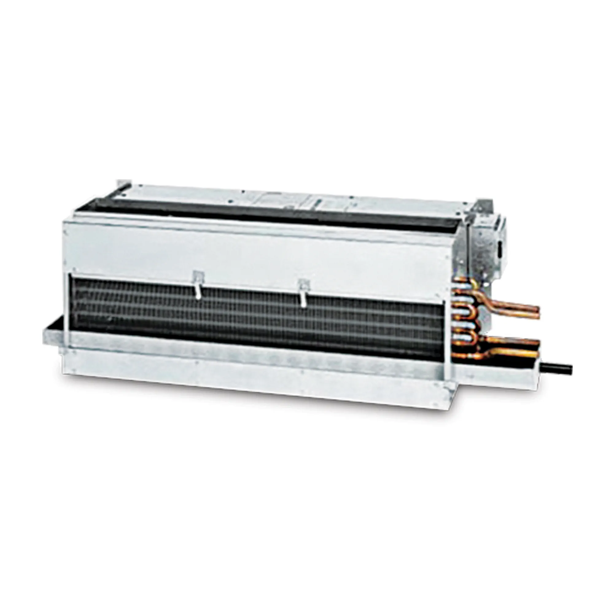
The Vertical Low-Silhouette Basic (F2-B) is a low-static (up to .25 ESP) top vertical discharge fan coil with a blow-through design. The F2-B fan coil comes with a coil, blower/motor assembly with quick-connect plug and a galvanized steel, powder-coated epoxy drain pan covered with ⅛-inch thick insulation. The galvanized steel cabinet is insulated with ½-inch thick, over three pound density, neoprene-coated fiberglass. The F2-B has a top-discharge duct collar. The 14½-inch high F2-B is designed for under-the-window furred-in applications with a field-fabricated, custom enclosure. This model has no exterior cabinet.

Cooling Capacity

F2 Series vertical fan coils have been rated in accordance with AHRI Standard 440-2005 for room fan-coils air-conditioners and are certified by AHRI to meet the following product performance ratings:

Based on 80°F DB and 67°F WB EAT, 45°F EWT, 10°F temperature rise, high fan speed. Motor voltage 115/1/60 power source.
Air flow under dry coil conditions. Water pressure drops shown in feet of water.

Heating Performance

Based on 70°F DB EAT, 180°F EWT, 40°F temperature drop, high fan speed. Motor voltage 115/1/60 power source.
Air flow under dry coil conditions. Water pressure drops shown in feet of water.

Features

  • 400 and 600 CFM
  • The Basic unit consists of heavy-gauge galvanized chassis, a drain pan, filter, motor/blower assembly and top-discharge duct collar
  • Designed for furred-in, under-the-window applications
  • Stands only 14½” in height and accommodates a field-furnished and installed custom enclosure that conceals unit
  • Low silhouette allows unobstructed window views
  • Coils are limited to four rows – two units may be set side-by-side where 800 to 1,200 CFM is required
  • Blow-through design
  • Coils are manufactured of copper tube with aluminum fins and are 100% underwater pressure tested to 350 PSI with a 300 PSI working pressure
  • Galvanized drain pan is finished with a powder-coated epoxy and covered with 1/8″ thick insulation
  • Heavy-gauge galvanized steel cabinet insulated with 1/2″ thick, over three-pound density, neoprene-coated fiberglass
  • Three-speed, 115/1/60 motor with quick-connect plug
  • Controls and motors are factory-wired and terminated in a junction box for single-point power supply
  • One-inch fiberglass, throwaway filter
  • Rear mounting holes provided for wall mounting
  • Protective covers keep the grille openings free of debris during shipment and construction
  • Individually tagged, crated and shipped as scheduled for installation
  • ETL and AHRI certified; 100% factory tested

Accessories

Accessories Options

  • Valve package controls – wide selection of factory-mounted valves and controls
  • Outside air dampers/wall boxes
    • Manual
    • Motorized
    • Bug screens
    • Leveling legs
  • TXV – factory-mounted
  • Condensate float switch
  • Condensate pumps
  • Thermostats

Dimensions

Options

Systems

  • DX
  • Chilled-Water
  • Hot-Water
  • Electric Resistance
  • Steam

In any combination of the above

Insulation

  • Thickness up to 1″
  • Fiberglass
  • Foil-face
  • Elastomeric

Coil

  • Copper fins/tubes
  • Phenolic-coated
  • Stainless-steel end plates
  • Right or left connections
  • TXV – factory-mounted
  • Freeze protection
  • Custom fin spacing

Drain Pan

  • Stainless-steel
  • Extended
  • Drip tray
  • Condensate float switch
  • Condensate pumps

Cabinets

  • Marine duty
  • Extensions
  • Heavier steel gauges
  • False back
  • Sub-base

Electrical

  • Motors
    • 115, 208, 230 and 277
    • Single or three phase
    • 50 or 60Hz
    • ECM
  • Line or low voltage
  • 1 to 5 kW electric resistance heat
  • Disconnects
    • Fused
    • Non-fused
  • Condensate float switch
  • Condensate pumps
  • Thermostats
  • UV Light
  • Controls
  • Flow Control

Further Information

• Right-hand unit shown, left-hand unit opposite.
• Coil connections determined by facing the supply-air opening.
• Electrical junction box is located on the same side as the coil connections.
• Unit must be installed level and condensate drain lines should be trapped.
• Drain pan is powder-coated epoxy with a 1/8” thick closed-cell insulation and has 3/4” NPT primary and secondary drain connections.
• Entire cabinet, scroll and blower wheel are heavy-gauge, galvanized steel.
• Coil Connections: 1/2” CW on F2004-006.