H3 R
High-Performance Horizontal Ceiling Mount

High Performance Horizontal Rear Return-Air Plenum

Part Number: H3-R

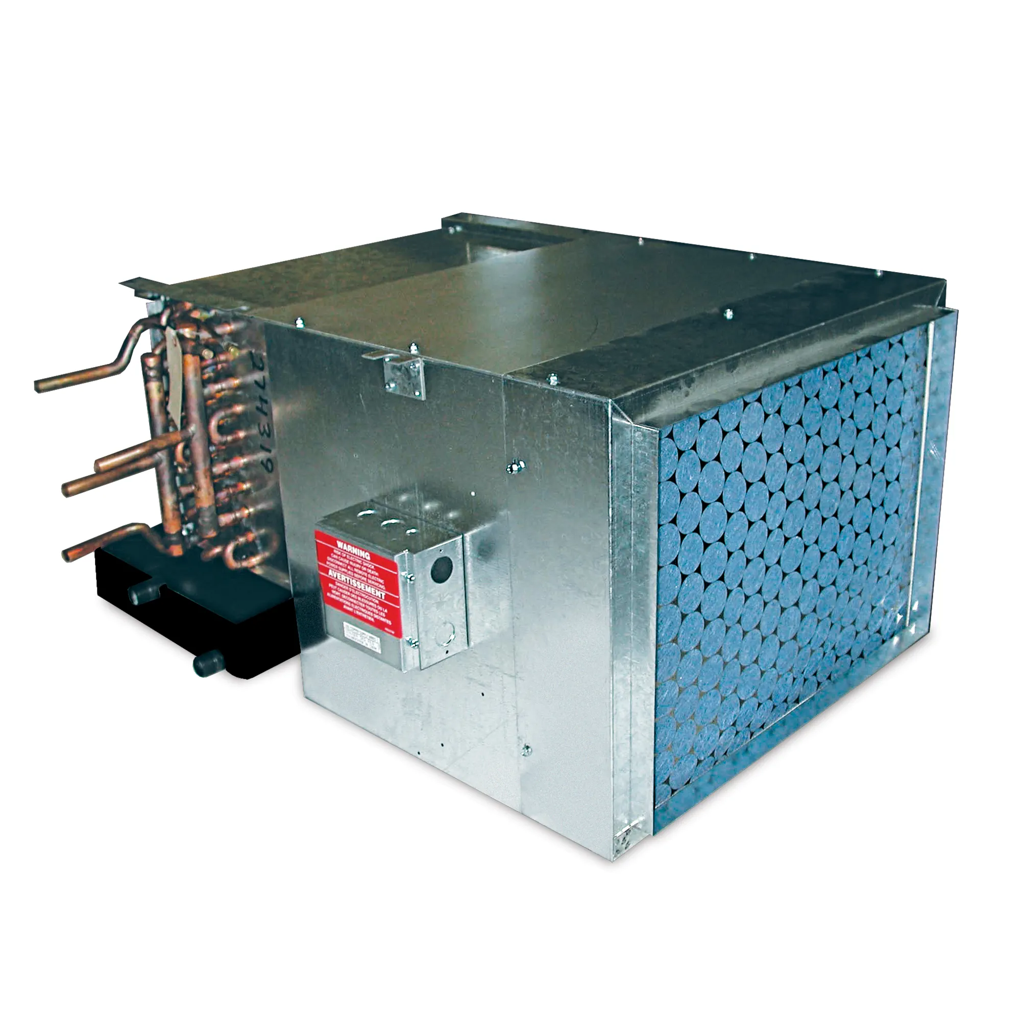
The High-Performance Horizontal Rear Return-Air Plenum (H3-R) is a high-static (up to .50 ESP) fan coil that comes with a coil, blower/motor assembly with quick-connect plug and a galvanized steel, powder-coated epoxy drain pan covered with ⅛-inch thick insulation. The galvanized steel plenum is insulated with ½-inch thick, over three-pound density, neoprene-coated fiberglass. The plenum conceals the fan and motor assembly that is easily accessed for service by removing the bottom panel. This unit is easily mounted above ceilings, in closets, and in hallways.

Cooling Capacity

H3 Series Hi-Performance Horizontal fan coils have been rated in accordance with AHRI Standard 440-2005 for room fan-coil air-conditioners and are certified by AHRI to meet the following product performance ratings:

Based on 80°F DB and 67°F WB EAT, 45°F EWT, 10°F temperature rise, high fan speed. Motor voltage 115/1/60 power source.
Air flow under dry coil conditions. Water pressure drops shown in feet of water.

Heating Performance

Based on 70°F DB EAT, 180°F EWT, 40°F temperature drop, high fan speed. Motor voltage 115/1/60 power source.
Air flow under dry coil conditions. Water pressure drops shown in feet of water.

Features

  • 400 to 2,200 CFM
  • Manufactured of heavy-gauge galvanized steel and insulated with 1/2″ thick, over three-pound density, neoprene-coated fiberglass; insulated drain pan with primary and secondary drain connections constructed of galvanized metal and finished with a powder-coated epoxy, easily removable motor/blower assembly with quick-connect plug and a galvanized rear return-air plenum
  • Ideal for mounting above ceilings, in closets, hallways or bathroom areas
  • The plenum conceals the blower motor which is easily accessible for servicing by removing the bottom panel
  • Access panel finished in a soft-white, powder-coated epoxy
  • No exterior cabinet
  • Coils are manufactured of copper tube with aluminum fins and are 100% underwater pressure tested to 350 PSI with a 300 PSI working pressure
  • Galvanized drain pan is finished with a powder-coated epoxy, 1/8″ thick insulation and features primary and secondary drain connections
  • Three-speed, 115/1/60 motor with quick-connect plug
  • Easy slide-out, blow-through blower and motor assembly
  • Controls and motors are factory-wired and terminated in a junction box for single-point power supply
  • One-inch fiberglass, throwaway filter
  • One-inch duct collar on return- and supply-air openings
  • High-static motor is designed for jobs where high-static pressure (0.50 max) is required
  • Protective covers keep the grille openings free of debris during shipment and construction
  • Individually tagged, crated and shipped as scheduled for installation
  • ETL and AHRI certified; 100% factory tested

Accessories

Accessories Options

  • Valve package controls – wide selection of factory-mounted valves and controls
  • Supply grilles
    • Single-deflection
    • Double-deflection
  • Thermostats
  • Condensate float switch
  • Condensate pumps
  • Controls – wide selection of factory-mounted valves and controls

Dimensions

Options

Systems

  • DX
  • Chilled-Water
  • Hot-Water
  • Electric Resistance
  • Steam

In any combination of the above

Insulation

  • Thickness up to 1″
  • Fiberglass
  • Foil-face
  • Elastomeric

Coil

  • Copper fins/tubes
  • Phenolic-coated
  • Stainless-steel end plates
  • Right, left connections or opposite end connection
  • TXV – factory-mounted
  • Freeze protection
  • Custom fin spacing

Drain Pan

  • Stainless-steel
  • Extended
  • Drip tray
  • Condensate float switch
  • Condensate pumps

Cabinets

  • Marine duty

Electrical

  • Motors
    • 115, 208, 230 and 277
    • Single or three phase
    • 50 or 60Hz
    • ECM
  • Line or low voltage
  • 1 to 9 kW electric resistance heat
  • Disconnects
    • Fused
    • Non-fused
  • Condensate float switch
  • Condensate pumps
  • Thermostats
  • UV Light
  • Controls
  • Flow Control

Further Information

For 600-1200 CFM models:

• All sizes shown in inches.
• Right-hand unit shown, left-hand unit opposite.
• Coil connections determined by facing the supply-air opening.
• Electrical junction box is located on the same side as the coil connections.
• Unit must be installed level and condensate drain lines should be trapped.
• Drain pan is powder-coated epoxy with a 1/8” thick closed-cell insulation and has 3/4” NPT primary and secondary drain connections.
• Entire cabinet, scroll and blower wheel are heavy-gauge, galvanized steel.
• Coil Connections: 1/2” CW on H3006, 3/4” on H3008-012 and 1/2” HW on H3006-012.

For 1500 to 2200 CFM models:

• All sizes shown in inches.
• Right-hand unit shown, left-hand unit opposite.
• Coil connections determined by facing the supply-air opening.
• Electrical junction box is located on the same side as the coil connections.
• Unit must be installed level and condensate drain lines should be trapped.
• Drain pan is powder-coated epoxy with a 1/8” thick closed-cell insulation and has 3/4” NPT primary and secondary drain connections.
• Entire cabinet, scroll and blower wheel are heavy-gauge, galvanized steel.
• Coil Connections: 3/4” CW on H3015-022 and 1/2” HW on H3015-022.
• Entire cabinet, scroll and blower wheel are heavy-gauge, galvanized steel.
• Coil Connections: 3/4” CW on H3015-022 and 1/2” HW on H3015-022.